End-to-end example
This example builds a five-storey residential bar from the default linear plan, simplifies every storey to perimeter and core zones, stacks the storeys, validates the building, and converts it with Convert2BEM and Convert2IDF. Every input value is given, and every expected result below was computed by BEMGen's own code with these inputs, so your definition should show exactly these numbers. The saved definition is end-to-end.gh in the examples zip of the release.
The definition
Dwelling Unit Preset ─┐
Corridor Preset ──────┼─► Linear Plan Generator ─► Perimeter Core ─► Merge (×3) ─► Stack Floors ─┬─► Validate
Stair Preset ─────────┘                                               Panel 1,3,1 ─┘   (Multipliers) ├─► Convert2BEM
                                                                                                    └─► Convert2IDF
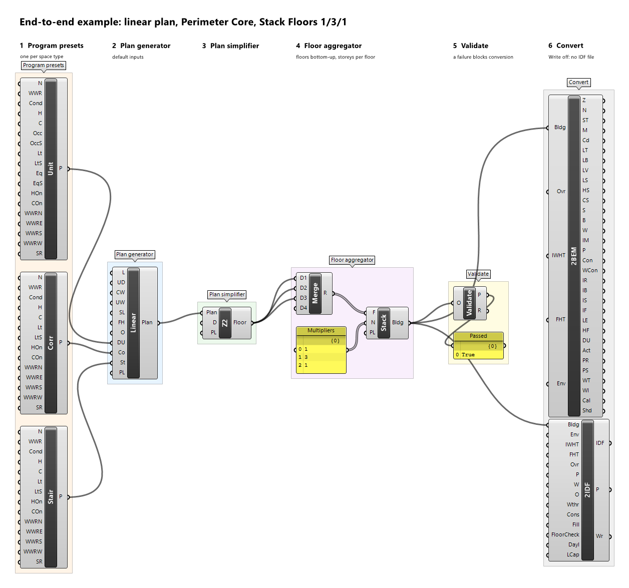
The saved definition end-to-end.gh: presets, generator, Perimeter Core, Merge and the multipliers panel, Stack Floors, Validate, and the two converters, each step in its own group.
1. Presets
Place Dwelling Unit Preset (Unit), Corridor Preset (Corr), and Stair Preset (Stair) from 1 Program Presets and leave every input at its default:
| Preset | WWR | Conditioned | Heating / Cooling | Loads |
|---|---|---|---|---|
| Example Dwelling Unit | 0.3 | yes | 21 °C / 24 °C | Occupancy 0.03 people/m², Lighting 5 W/m², Equipment 5 W/m² |
| Example Corridor | 0.2 | yes | 21 °C / 24 °C | Lighting 5 W/m² |
| Example Stair | 0.1 | no | — | Lighting 3 W/m² |
The presets have no infiltration. The building's infiltration comes from the envelope preset, here the Example Envelope's 0.3 air changes per hour, always on (step 6).
2. Linear Plan Generator
Place Linear Plan Generator (Linear) from 2 Generate, wire the three Preset outputs into Dwelling Unit (DU), Corridor (Co), and Stair (St), and keep the defaults:
| Input | Nickname | Value |
|---|---|---|
| Length | L | 24 m |
| Unit Depth | UD | 8 m |
| Corridor Width | CW | 2 m |
| Unit Width | UW | 10 m |
| Stair Length | SL | 4 m |
| Floor Height | FH | 3 m |
| Orientation | O | 0° |
| Preview Location | PL | 0, 0, 0 |
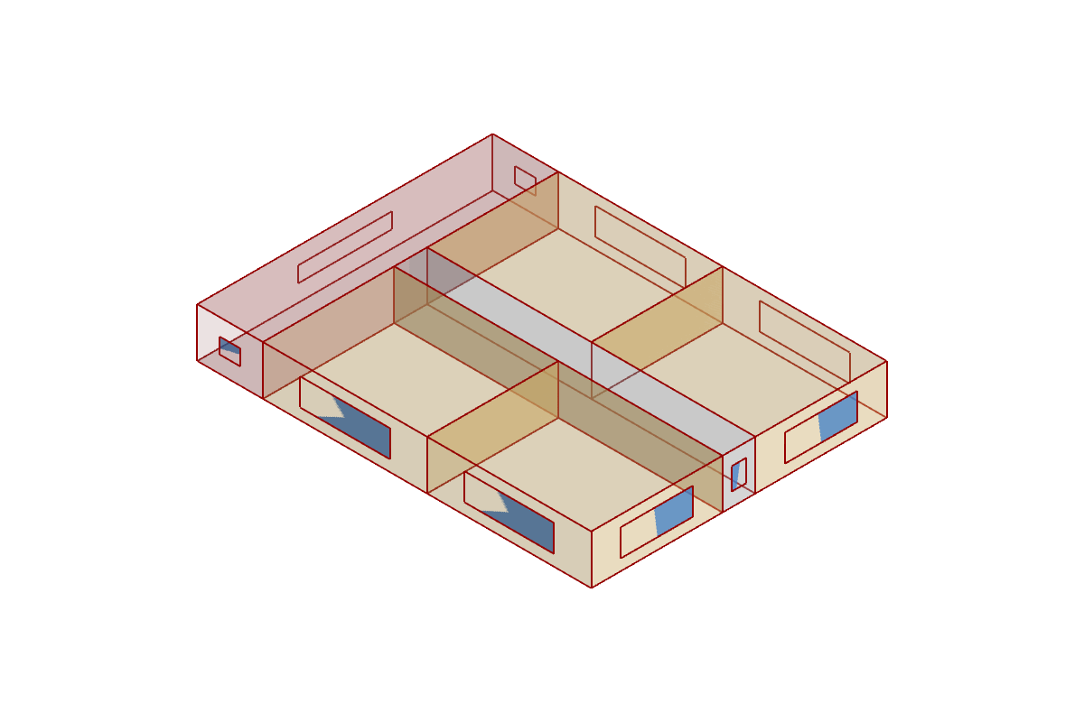
Expected Plan: Plan (6 zones, LinearPlanGenerator), 24 m × 18 m, 432 m².
| Zone | Space type | Area |
|---|---|---|
ST |
Stair (unconditioned) | 72 m² |
CO |
Corridor | 40 m² |
US1, US2 (south row) |
DwellingUnit | 80 m² each |
UN1, UN2 (north row) |
DwellingUnit | 80 m² each |
The plan has 10 windows with 59.4 m² of glazing: 19.2 m² facing north, 15.6 m² east, 19.2 m² south, and 5.4 m² west.
3. Perimeter Core
Place Perimeter Core (Z2) from 3 Simplify, wire the Plan into its Plan input, and keep Depth (D) at 4.57 m.
Expected Floor: Floor (5 zones, PerimeterCore), every zone of space type Mixed and conditioned:
| Zone | Area | Source zones |
|---|---|---|
P-North |
88.7951 m² | ST, UN1, UN2 |
P-East |
61.3751 m² | CO, US2, UN2 |
P-South |
88.7951 m² | ST, US1, US2 |
P-West |
61.3751 m² | ST, CO, US1, UN1 |
CORE |
131.6596 m² | CO, US1, US2, UN1, UN2 |
The floor still has 432 m² and 59.4 m² of glazing, now as 4 windows, one centred on each façade (19.2 m² north, 15.6 m² east, 19.2 m² south, 5.4 m² west); the core has no outdoor wall and no window. Validate on this floor gives Passed True, with one note: note ConditionedFloorArea: reference 360.000000, actual 432.000000, because the unconditioned stair is now part of conditioned perimeter zones.
4. Stack Floors with multipliers 1, 3, 1
Grasshopper keeps one wire per source and input: wiring Perimeter Core's Floor output into Floors three times leaves a single wire and a single floor. So the floor goes through Grasshopper's native Merge component (Sets tab): place Merge, wire Perimeter Core's Floor output into its inputs D1, D2, and D3 (Merge adds a new input each time its last one is connected, so a spare D4 stays empty), and wire Merge's Result, a list of the same floor three times (the ground storey, the middle storeys, the top storey, bottom-up), into Stack Floors' Floors (F). Place Stack Floors (Stack) from 4 Aggregate. For Multipliers (N), place a Panel with the three lines
1
3
1
and Multiline Data off, so that it outputs one item per line, and wire it into Multipliers. Stack Floors repeats each floor by its multiplier, so the building has 1 + 3 + 1 = 5 explicit storeys. This is how end-to-end.gh is wired.
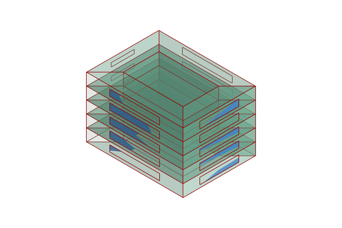
Expected Building: Building (25 zones, Stack):
| Quantity | Value |
|---|---|
| Zones | 25: L0/P-North, L0/P-East, L0/P-South, L0/P-West, L0/CORE, then the same for L1 to L4; every zone multiplier 1 |
| Floor area / volume / height | 2160 m² / 6480 m³ / 15 m |
| Surfaces | 150: 100 walls (20 outdoor, 80 between zones) and 50 floors and ceilings (5 on the ground, 40 between storeys, 5 roofs) |
| Exterior wall area | 1260 m² |
| Windows | 20, with 297 m² of glazing: 96 m² north, 78 m² east, 96 m² south, 27 m² west |
| Provenance (first line) | Stack Multipliers=1,3,1 […] |
The numbers on this page were computed for three identical Perimeter Core floors with the multipliers 1, 3, 1, which is exactly the building of end-to-end.gh.
5. Validate
Place Validate from 6 Inspect and wire the Building into Object. Expected: Passed True. The Report starts with PASSED, then the checks of the one distinct source floor against its plan (Floor0.…, with the conditioned-area note above) and of the building against the fully stacked reference (Building.…), for example:
  ok   Building.FloorArea: reference 2160.000000, actual 2160.000000
  ok   Building.Glazing: reference 297.000000, actual 297.000000
  ok   Building.Installed.Lighting: reference 10080.000000, actual 10080.000000
  ok   Building.GroundArea: reference 432.000000, actual 432.000000
  ok   Building.RoofArea: reference 432.000000, actual 432.000000
  ok   Building.Height: reference 15.000000, actual 15.000000
6. Convert2BEM
Place Convert2BEM (2BEM) from 5 Convert and wire the Building. Leave Override, EnableInternalWallHeatTransfer, and EnableFloorHeatTransfer at False and Envelope unconnected (the Example Envelope is used).
| Output | Expected |
|---|---|
| Zones, Names, Space Types, Multipliers, Conditioned | 25 branches {0} to {24}; names L0/P-North … L4/CORE; every space type Mixed, multiplier 1, conditioned True |
| Load Types / Load Bases | 3 per zone: Occupancy, Lighting, ElectricEquipment (all PerFloorArea) |
| Load Values | e.g. L0/P-North: 0.027297, 4.81981, 4.549525; L0/CORE: 0.023228, 5, 3.871332 (rounded) |
| Load Schedules | 75 branches {i;k} of 8760 values |
| Heating / Cooling Setpoints | 8760 values per zone, 21 °C and 24 °C |
| Surfaces / Boundaries / Constructions | 6 per zone, 150 in all. Boundaries: 20 Outdoors walls, 80 Adiabatic walls, 5 Ground floors, 40 Adiabatic floors and ceilings, 5 Outdoors roofs. Constructions: Example Exterior Wall, Example Interior Wall, Example Ground Floor, Example Interior Floor (floors above a storey), Example Interior Floor Reversed (ceilings below one), Example Roof |
| Windows / Window Constructions | 20 windows, one per perimeter zone and storey; each Example Double Glazing; the CORE zones have no branch |
| Internal Mass | 0 for every zone |
| Provenance | the provenance tree, the validation report, OPTIONS: EnableInternalWallHeatTransfer=False EnableFloorHeatTransfer=False, ENVELOPE: Example Envelope, INFILTRATION: 0.3 AirChangesPerHour (EnergyPlus AirChanges/Hour), schedule Example Always On |
| Infiltration Rate / Infiltration Basis | 0.3 / AirChangesPerHour, the same for every zone |
| Infiltration Schedule | 8760 values, all 1 |
| Infiltration Flows | 25 branches {0} to {24}, one number each, 0.3 times the zone's volume in m³: e.g. L0/P-North 79.9156, L0/P-East 55.2376, L0/CORE 118.4936 (rounded) |
Set both heat-transfer options to True and the 120 adiabatic surfaces become Interzone:<zone ID>, for example a wall of L0/P-North against the core is written Interzone:L0/CORE.
7. Convert2IDF with Write off
Place Convert2IDF (2IDF) from 5 Convert and wire the Building. Leave Envelope unconnected, EnableInternalWallHeatTransfer, EnableFloorHeatTransfer, and Override False, Path empty, and Write False and Overwrite False.
| Output | Expected |
|---|---|
| IDF | the full IDF text; the component shows one remark, NoWeatherFile, because no weather file is connected |
| Written | False |
| Provenance | ends with ENVELOPE: Example Envelope, INFILTRATION: 0.3 AirChangesPerHour (EnergyPlus AirChanges/Hour), schedule Example Always On, ENERGYPLUS: 26.2, SHADING: none (every storey is modelled), WEATHER: none given (…), GROUND: indoor minus 2 C; 20.5, … (twelve times 20.5: the 21 and 24 °C setpoints' midpoint minus 2), and FILE: not written (Write is false) |
The IDF holds 25 Zone objects, 150 BuildingSurface:Detailed, 20 FenestrationSurface:Detailed, 25 each of People, Lights, ElectricEquipment, and ZoneInfiltration:DesignFlowRate (the last one per zone, from the envelope preset, in EnergyPlus's air-changes-per-hour method), 25 thermostats with ideal-loads air systems, 8 materials, 1 simple glazing, 7 constructions (the six above and the window construction Example Double Glazing), monthly ground temperatures of 20.5 °C, and the hourly outputs: 5 output variables (the zone mean air temperature and four ideal-loads quantities) and 9 meters (heating, cooling, electricity, interior lights, and interior equipment), with the summary tables and SQLite output.
To write the file, give Path a fully qualified path in an existing folder, for example C:\models\end-to-end.idf, and set Write to True; Written becomes True and Provenance ends with FILE: written C:\models\end-to-end.idf. To simulate, connect a weather file to Weather, for example C:\EnergyPlusV26-2-0\WeatherData\USA_IL_Chicago-OHare.Intl.AP.725300_TMY3.epw: the IDF then holds Site:Location for Chicago, and Provenance holds WEATHER: USA_IL_Chicago-OHare.Intl.AP.725300_TMY3.epw sha256 …. Run it in EnergyPlus 26.2 with the same weather file; BEMGen does not run EnergyPlus.
Variations to try
- Replace Perimeter Core with Single Zone per Floor: each storey becomes one zone, and the building has 5 zones with the same 2160 m², 297 m² of glazing, and loads.
- Replace Perimeter Core with Conditioned Merge: each storey becomes two zones,
Conditioned-1(360 m²) andUnconditioned-1(the 72 m² stair), so the building has 10 zones and 60 surfaces, with the same 2160 m² and 297 m² of glazing. Validate passes with no note, because the conditioned floor area, 1800 m², is exactly that of the five plans. The stair is a zone without HVAC, so its walls toward the conditioned zone, and its floors and ceilings between storeys, are writtenInterzone:<zone ID>even with both heat-transfer optionsFalse. - Replace Stack Floors with Stacked Floor Zone Multiplier: the three middle storeys are modelled once, by storey
L2at its true elevation with zone multiplier 3, so the building has 15 zones (provenanceStoreys=L0x1,L2x3,L4x1); storeysL1andL3are drawn transparent grey, and the totals that Validate checks stay the same. - Change Orientation to 90: the geometry stays, but every façade's orientation changes, so the glazing per orientation in the validation report changes accordingly.